Building Wall Heat Transfer Calculator
Model one-dimensional steady-state heat transfer through a plane wall with 1–7 layers. Calculate thermal resistance, U-value, heat flux, total heat flow and the temperature at every wall interface.
Calculate heat transfer through a multilayer building wall
This building wall heat transfer calculator evaluates one-dimensional steady-state heat flow through a wall made of one to seven solid layers. For every layer you can enter the thickness and thermal conductivity, while the indoor and outdoor convection coefficients account for the two surface resistances. The model then calculates total thermal resistance, U-value, heat flux, total heat flow and the temperature at each wall interface.
The tool is useful for comparing wall assemblies, testing insulation options and understanding where temperature drops occur through a multilayer construction. The original CleanEnergy4Future schematics are displayed automatically for the selected number of layers, making the thermal-resistance network and interface temperatures easier to interpret.
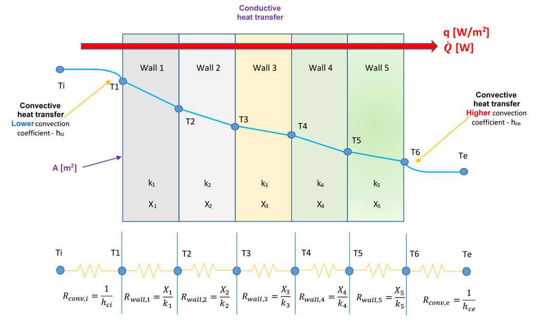
Heat-transfer model for 5 wall layers
The schematic follows the same 1–7 layer resistance-network configuration used by the original CleanEnergy4Future application. Change the number of wall layers below and the diagram updates automatically.
Wall & boundary inputs
Wall layers
Indoor → outdoorMaterial presets are illustrative starting values. For engineering work, enter the thermal conductivity from the product, standard or project documentation you are using.
Thermal performance
Temperature profile through the wall
| Layer | Thickness | k | R | T in | T out | ΔT |
|---|
Resistance contribution by layer
Insulation thickness for a target U-value
This is an engineering target calculation, not an economic optimum. It finds the added resistance and insulation thickness needed to reach the U-value you specify.
R-value, U-value, heat flux and interface temperatures
Each wall layer contributes a thermal resistance equal to its thickness divided by its thermal conductivity. Materials with a lower conductivity or a greater thickness provide more resistance to conductive heat transfer. The calculator adds the resistances of all layers to the indoor and outdoor convective surface resistances to obtain the total R-value of the modeled assembly.
The wall U-value is the reciprocal of total thermal resistance in this model. A lower U-value means less steady-state heat transfer for the same indoor-to-outdoor temperature difference. The calculated heat flux q expresses heat transfer per square metre, while total heat flow Q also accounts for the wall area. These outputs make it possible to compare alternative wall constructions on a consistent physical basis.
Why the temperature profile matters
The temperature profile shows the calculated temperature at the indoor surface, at every material interface and at the outdoor surface. A large temperature drop across one layer indicates that the layer contributes a relatively large share of the total thermal resistance. Moving insulation from the exterior to the interior does not change total resistance in this idealized one-dimensional steady-state model when its properties remain unchanged, but it does change the temperatures inside the wall assembly.
Insulation thickness for a target U-value
The target-U explorer calculates the additional thermal resistance needed to reach a selected U-value and converts that resistance into an insulation thickness using the entered insulation conductivity. It is useful for preliminary comparison of insulation options, but it is not an economic optimum: real retrofit decisions can also depend on climate, moisture behavior, thermal bridges, installation constraints, material cost, energy price and service life.
Typical uses
- Calculate the U-value and R-value of a one- to seven-layer wall.
- Compare brick, concrete, plaster, wood, aerated concrete and insulation layers using editable conductivity values.
- Estimate steady-state wall heat loss or heat gain for a known wall area and temperature difference.
- Visualize temperature drops across individual layers and wall interfaces.
- Estimate the insulation thickness required to reach a target U-value before carrying out a more detailed building-energy assessment.
Building wall heat transfer FAQ
How many wall layers can I model?
The calculator supports one to seven solid wall layers. Each layer can have its own name, thickness and thermal conductivity.
What is the wall U-value?
For this steady-state model, U is the reciprocal of the total thermal resistance, including all conductive wall layers and the indoor and outdoor convective boundary resistances.
Does moving the same insulation from outside to inside change the U-value?
Not in this one-dimensional steady-state resistance model when insulation thickness and conductivity are unchanged. The total resistance remains the same, but the temperature distribution through the wall changes.
Is the target-U insulation result an economic optimum?
No. It is the insulation thickness required by this thermal-resistance model to reach the selected target U-value. Economic optimization requires additional assumptions about energy prices, climate, investment cost and service life.
For cost-focused insulation analysis, also see the Insulation Savings Calculator and Insulation Project Cost Calculator.
Method used
The calculator uses the steady-state thermal-resistance network for a plane multilayer wall with convection at both surfaces.
Rᵢ = xᵢ / kᵢx = layer thickness [m]; k = thermal conductivity [W/mK].
Rconv,i = 1 / hᵢ Rconv,e = 1 / hₑh = convective heat-transfer coefficient [W/m²K].
Rtotal = 1/hᵢ + Σ(xᵢ/kᵢ) + 1/hₑ U = 1/Rtotalq = (Tᵢ − Tₑ) / Rtotal Q = q · Aq is heat flux [W/m²]; Q is total heat flow [W].
Model scope & limitations
- One-dimensional, steady-state heat flow through plane homogeneous layers.
- No internal heat generation inside the wall.
- Thermal conductivities are treated as constant input values.
- Radiation, thermal bridges, moisture transport and transient thermal storage are outside this calculator.
- The target-U explorer calculates required thermal resistance, not life-cycle economic optimum thickness.
Related WattCostLab tools
Learn wall heat transfer, R-value and U-value
Use these guides to understand the equations, assumptions and units behind this calculator.